Drake TR-3 Restoration
IMO, this is the King of Rigs. This was the, or one of the first, dedicated Amateur Radio transceivers, not a pair of boat anchors repurposed for Amateur use.
This radio is still a work of art from its 300 W SSB input, more than enough to drive any Ham linear, to the trademark 'blue glow' of the VFO dial and meters.
The TR-3 was also used mobile, my Grandfather/Elmer K8BYP used one in his car while on vacation in FL many years ago. There was a vibrator power supply to convert 14V from the car alternator.
Drake was in Miamisburg, (Dayton) OH, which was and still is a major hub for the most unbelievably high-tech science and engineering in the world. This Drake equipment was state of the art and very high quality, only exceeded in most opinions by the Collins Twins at a much higher price.
This particular radio came to me thanks to Perry KK4LZF on a bit of a dare- for him to go to the Hamfest and find a TR-3 for me to restore. Gramps had one, I wanted one to redo and use.
Not only did he find one, but only one and it was in excellent condition. There are several things inside that lead me to believe this rig has had little time on the air:
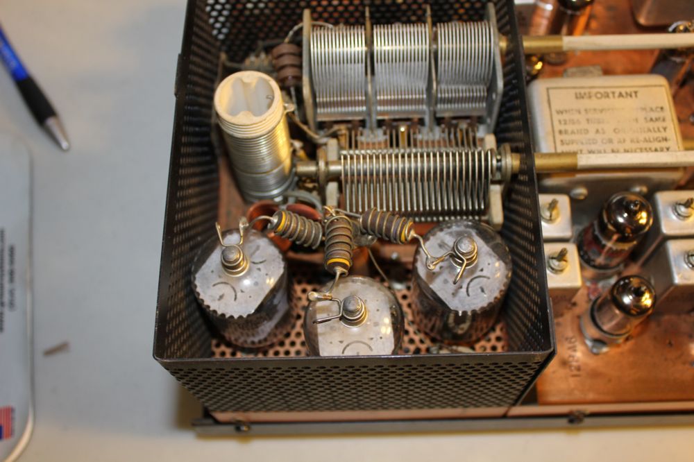
1. The final tube plate cap springs are not oxidised as they should be if the finals had been hot for a significant length of time
2. The AF and RF gain pot traces had no wear. The TX gain had quite a bit of wear.
3. The neutralization air variable cap was set wide open. Not a good sign.
4 Theres not a mark on the front panel, no wear on the knobs
5. The REALLY telling sign is the red button on the upper right side of the VFO knob- thats a slider for the VFO index mark and in this old rig, that red button is always faded and worn due to being handled with fingers. It looks like new.
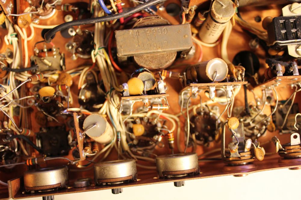
I've worked on more old tube TVs and radios than I can count. This TR-3 is one of the most difficult piece I've ever worked on. Its mostly point-to-point wired, which is common in old tube equipment that pre-dates printed wiring boards, but the components in this rig are built in layers and some of the components such as the air variable in the TX drive are so buried in rats nests I'm not going to remove it, it'll have to be reconditioned in place. The TR relay is also built in like a tank, the contacts showed almost no wear or arcing, only a slight black shadow of carbon came out when the contacts were cleaned.
It is difficult and delicate work, but many of the caps will be changed, all the electrolytics and tubular papers, most of all of the grid to plate coupling caps - even a slight leakage in one interstage coupling capacitor will really mess up grid bias on the next stage or possibly damage a tube. Since parts are no longer available for these old radios, restoration is done without having a ready parts source, so one must be extra careful to not break anything that's not already broken.
Pix:
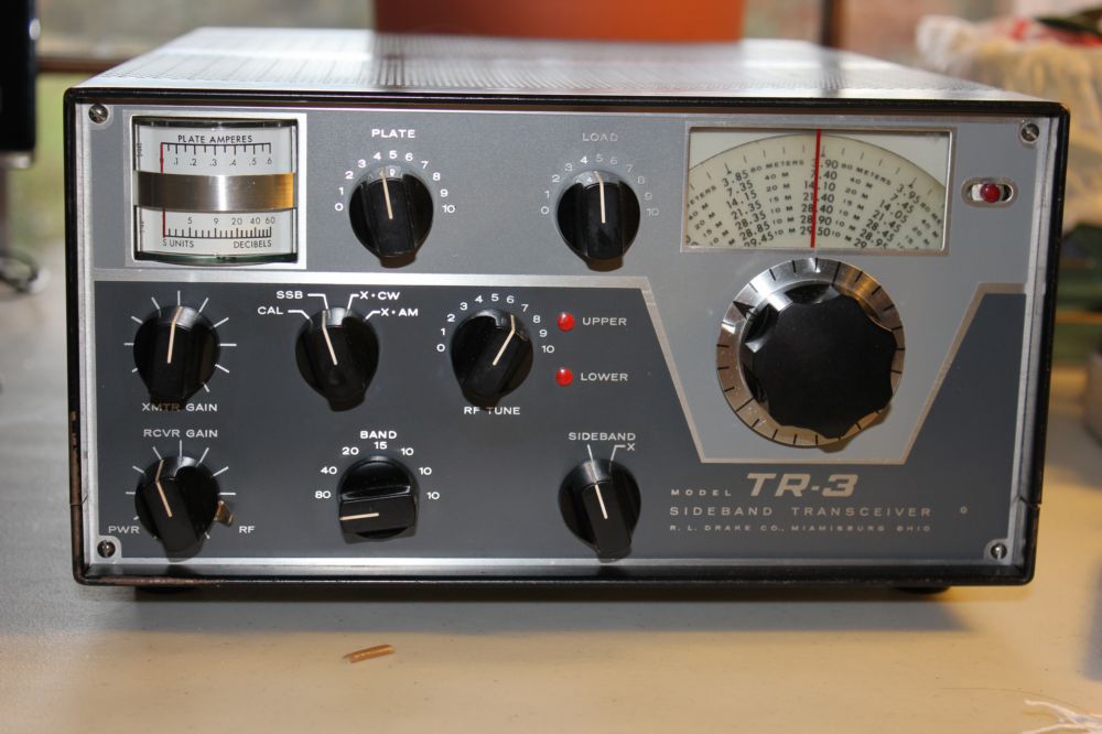
#1. Front view, no wear on black knobs. There should be whitish shadows on the sides where the fingers touched them. The VFO dial is dirty and yellowed, that discoloration washed off.
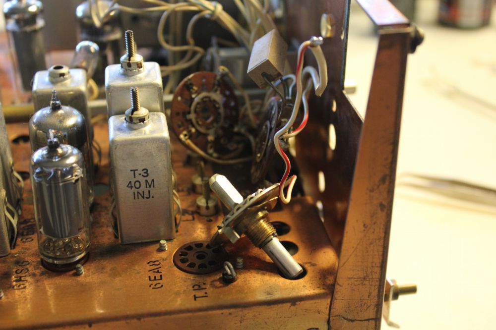
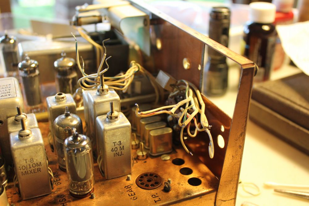
#3 Air variable TX caps were removed for cleaning and lube. The trick is to remove the shorting springs from one of them, unsoldering them, to remove and clean under them. Without good contact from the shaft to the body through these springs, the cap will not work properly.
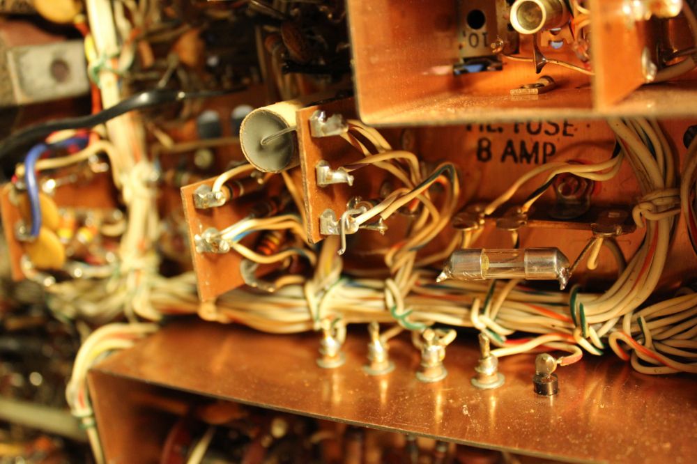
4,5 Close up view of the rats nest underneath. Look at #4 closely, here's a resistor that was installed but never soldered. It was placed across the plate current meter but had no effect in the circuit-an assembly mistake.
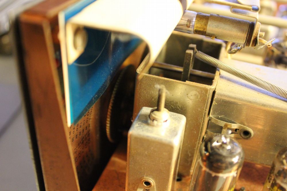
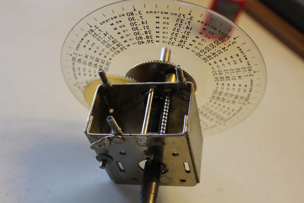
#6 VFO assembly, the blue plastic behind the dial is the source of the blue glow. A similar blue plastic filter is behind the twin meters on the front left.
#7 The TX mode switch disassembled, not only do the switch contacts (wafers) have to be deoxidised, but the mechanical detent cleaned and lubed. The trick is to NOT use Tarn X straight from the bottle on these silvered contacts, but dilute it 50% with filtered water.
The band and SSB filter switches are of the same design and need the same work.
# 8 Meters and AF/RF pot removed
#9 VFO mechanism and dial reconditioned. The dial came out about like new!
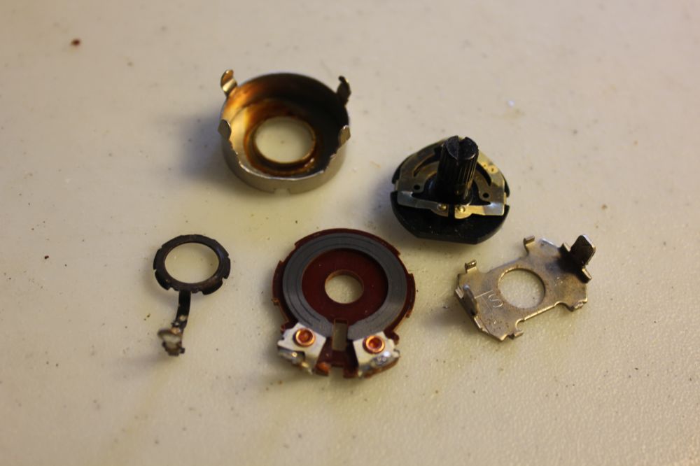
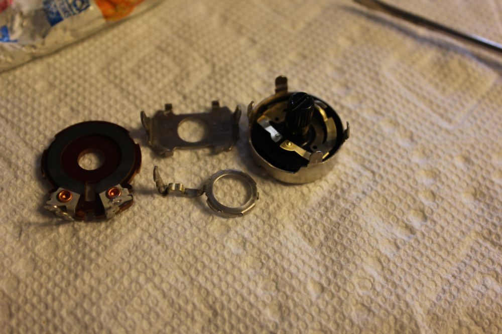
#10 XMIT gain pot cleaned and lubed. Careful handling is required to disassemble these without breaking the housing tabs that hold this kind of pot together. I broke a few in the TV repair days!
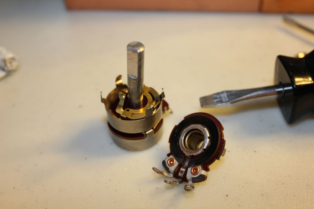
#11 AF/RF gain / Off-On switch pot disassembled for reconditioning.
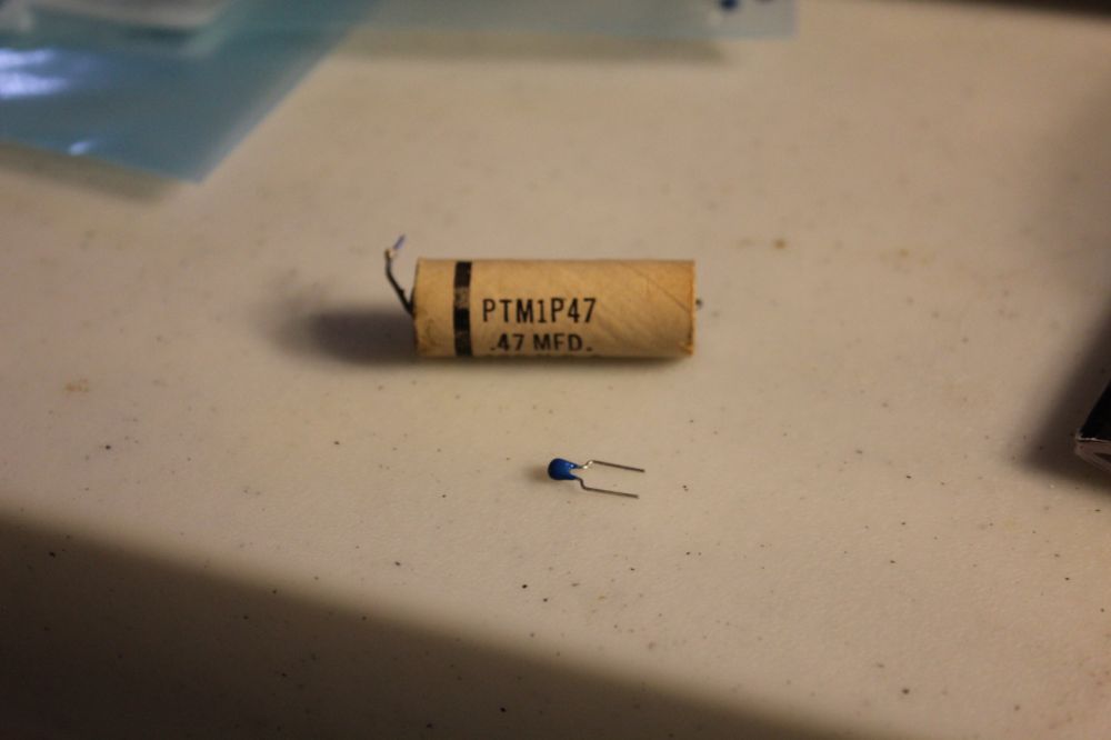
# 12 There are several tubular caps, 0.1-0.47 uF, 100V such as this, the replacements are a fraction of the size of the original. With smaller caps then, there wouldn't have been the need for the large terminal boards.
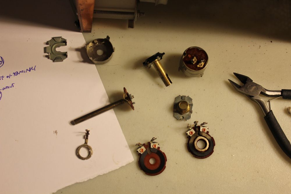
#13 & 14 Pot in power supply, before and after. Notice the center wiper terminal is black from oxidation.
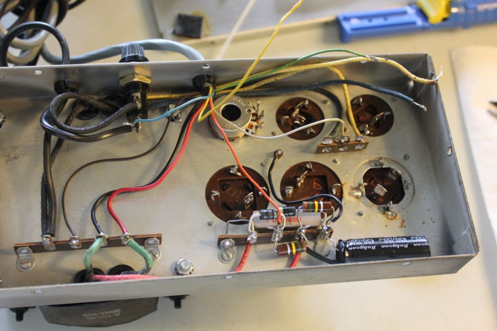
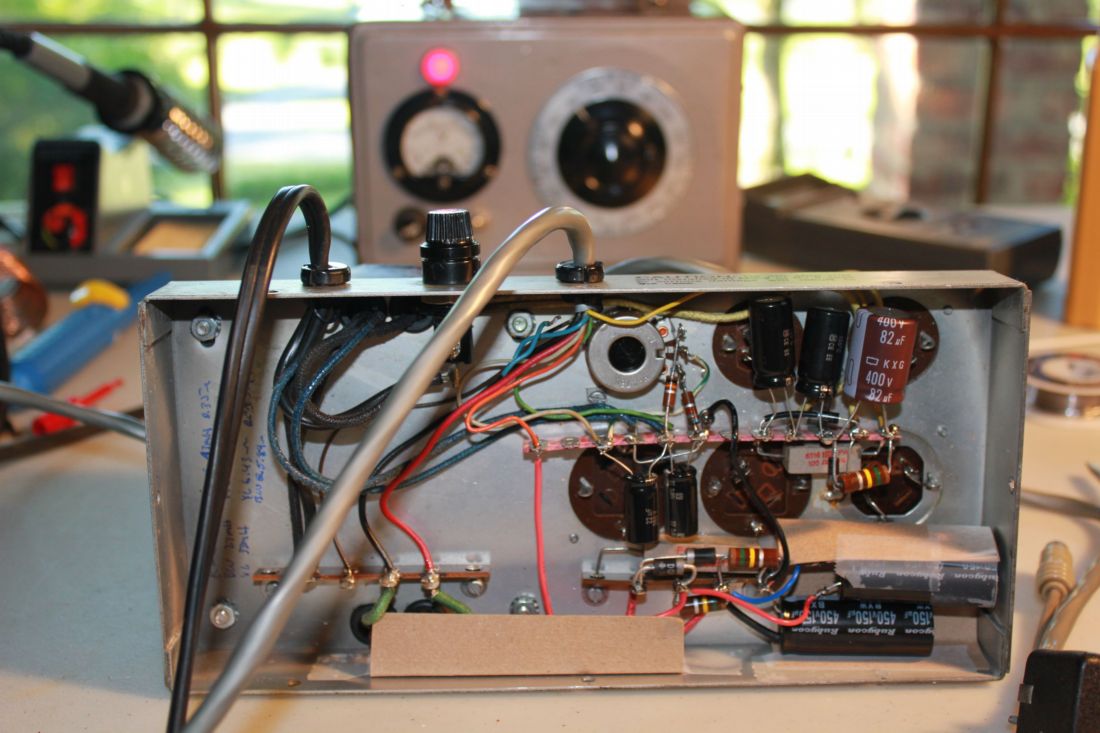
#15 Complete re-wiring of power supply, the factory job was HORRIBLE- a true 'rats nest'
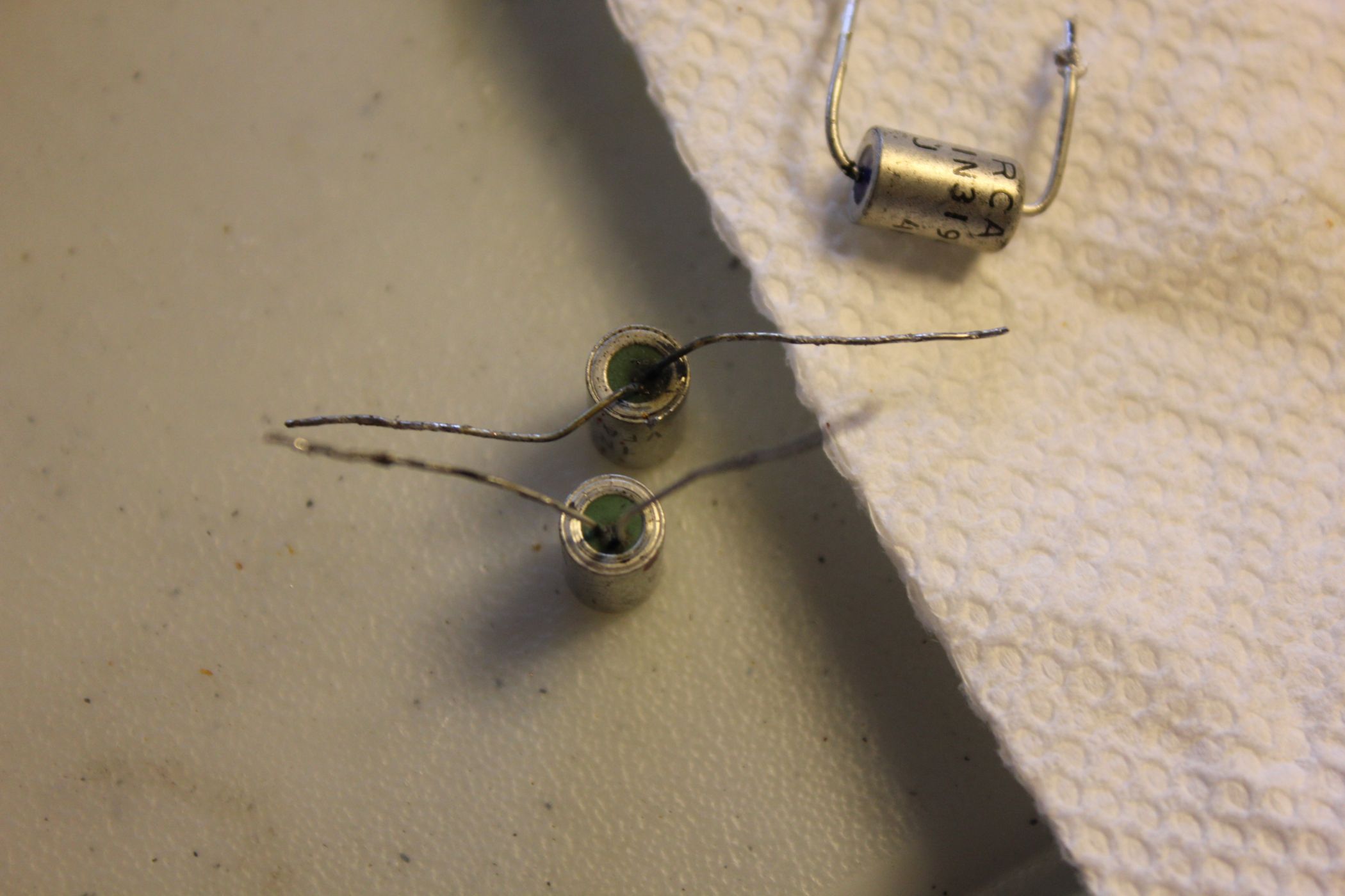
#16 Why to replace the old rectifier diodes (and these are about as old as it gets!) ? Two were damaged, not the junctions, but the lead wires were close together and both close to a sharp metal edge on the case, the potting compound (some kind of epoxy?) was darkened from leakage current. WHen that current gets high enough, arcing ocurrs.
Modern high PRV rectifiers were put in their place, eliminating two diodes.
#17 PS totally rebuilt, the wiring and parts placement arent original (which was very poorly done) but is "period'. A terminal strip was added on which to wire the 250 and -50 V supplies. The unit was burned in for a day on a variac to make sure nothing could short on initial power-up to cause damage to the radio.
Below, first picture, the tuning dial is dirty and appears a bit yellow, that all washed off (fortunately the numbers didn't wash off!)
Update, 7/16
Lots of out of tolerance resistors, the cathode resistors in the RF final are severely under-rated and overheating (I assume) has caused their values to change. Higher wattage units were put in the TR-4.
PS THIS IS A BRAND NEW RADIO. It had defects, including a missing component, that meant it never could have been operated to even align it at the factory. Its never been on the air!