This page chronicles my development of a couple odd, very efficient vertical antenna, one for HF and one for 2M. Part of the goal was to make both generally of the same design so what
was learned on one could be applied to the other. This only succeeded to a
degree and that mostly of studying antenna mounting.
The antenna are sort of 'twins', they were designed and tweaked in parallel. The 2M version is much easier to hold in ones hand, compared to a 20 foot tall, 40 lb. steel pole, but is much more critical as to parasitics, so in the end, the usefulness in comparing the two was limited.
There's not supposed to be, in the Amateur world, such a thing as:
1. A vertical that actually works without a SWR of 2+ even with radials and loading coil,
2. A beam with less than two elements
We can look anywhere in town and see Public Service Band verticals on towers up as much as a hundred feet, problem is, they usually have radials. Radials stink, they break easily.
There are two general types of antenna:
1. with one connection (verticals or "monopoles")
2. with two connections (dipoles and loops)
It is impossible to load a feedline into a vertical because the vertical has only one place to attach a wire, and that's usually at the bottom. A loop brings the other end of a straight conductor around to connect to the other feedline conductor. There is no place to attach the second conductor of the feedline to a monopole, so, the feedline sees an open circuit and thus power cannot be efficiently transferred from feedline to antenna.
There are two ways to couple the two-conductor feedline to a vertical:
1. The miserable, extremely lossy method of ground radials. Radials only work and work efficiently on paper, as a perfectly conducting ground plane is required. This perfect plane is a simplifying assumption to allow calculation of antennae. Radials are an electro-static coupling, like connecting a capacitor between the feedline shield and antenna.
Problem is that radials over real ground are horribly lossy, imagine a dipole with both arms radiating- then bury one in the ground-a sad waste of power.
2. Shunt feed. This is common in the commercial world, referenced in the 1958 ARRL Handbook, but poorly described in the Handbook, and not common in the Amateur world.
Stop and think about so called 'ground radials' - what if the antenna is 10 wavelengths above the ground? Then they are no longer ground radials!
The reason verticals work poorly is not about the antenna, its the Frankenstinian method of attempting to load the end of the feedline with radials. The system is then highly capacitive then requiring a large tapped inductor which brings its own set of problems.
In short, they never work well, often described as "high SWR antennas."
If radials actually worked, why is there a need for a bulky loading coil? THEY DONT WORK!
The shunt design is common to many 'beam' antennas. Its referred to as a Gamma Match. This vertical is basically an ordinary beam with half the driven element and all the parasitics removed. It works fine, but one might think it would not be very directional.
It is quite directional- a somewhat subjective S-5 in directionality. Thats quite a bit of gain for a junk box antenna with only one element! It's a strange sight to see it mounted upon a pole with a rotor!
Read about the popular J-pole antenna, described as being generally directional due to the J section being in parallel with the antenna.
An antenna shunt system (shunt and portion of the antenna in parallel with the shunt)
is basically two inductors in parallel. By laws of inductors, if the current flows in opposite directions in each element and they are in parallel, their mutual inductance causes cancellation in between the inductors- no magnetic field. No M field, no propagation.
The general form is (2L-2M).
The result is that the M field is not present away from the sides of the antenna and shunt, theres more or less a null on the sides between the antenna and shunt.
In a gamma matched Yagi, the shunt section is generally rather short, and the directionality is a function of having a large antenna with as many parasitic elements as possible, the more the better.
What causes the directionality in this antenna is the relatively long length of shunt tubing parallel to the antenna. The shunt section is about 25 inches compared to a 72 inch full wave pole for 2M, a third of the overall antenna length.
The biggest problem with this antenna and, any at VHF and above, is the parasitics of the mounting structure. The parasitics end up not influencing, but controlling the antenna dimensions and tuning and not in a happy way.
The best was found to be a minimal amount of any insulating material between the shunt and antenna (some is required for mechanical stability at the base) and mounting the antenna by a wooden pole (high dielectric constant) up inside the bottom of the antenna. There are no fields inside the tube, so no energy is transferred anywhere (we hope) by contact with the wooden pole. Its an oak pole for strength.
Better yet, possible at VHF and above, is to suspend the antenna from a 'yard arm' to completely eliminate feedpoint interaction with any mounting structure. This turns out to not be a practical mouting for operation. Such an installation is for testing and at VHF, it is essentially an isotropic mounting scheme. (the antenna is not affected by anything else if its high enough above the ground)
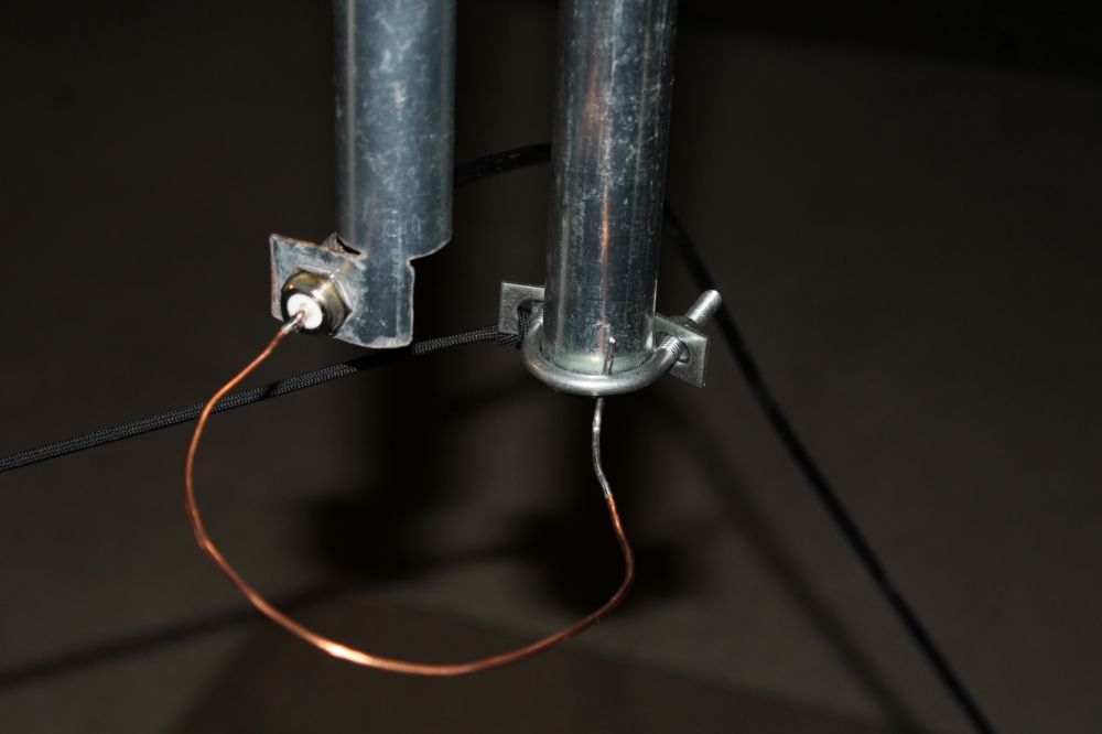
It is not sufficient to connect the feedline shield to the shunt, it was necessary to put a small inductance in between the two. Initially a wire loop reminiscent of an old UHF TV antenna loop, was used to provide a small L. The loop is mechanically and electrically very unstable, so a proper wound coil was used when the antenna was put in final form. The loop has a high interaction with surrounding fields, the wound coil much less so. The coil was potted in polyurethane spray foam which has a dielectric constant about the same as air, so the coil could not become wet (water= high dielectric constant) and the water change the antenna tuning.
The antenna absolutely refused to tune to 50 ohms until a short gimmick wire was soldered to the antenna just above the top of the shunt tube. Why I do not know and do not care, it works great!
What's as amazing as the gain is the wide SWR bandwidth (there is really no such thing as BW in an antenna, we are concerned with the bandwidth at an acceptable SWR. BW is a parameter of amplifiers, not so much for antennas. We dont look at a -3 dB point on an antenna, we want to know where the SWR goes to crap.)
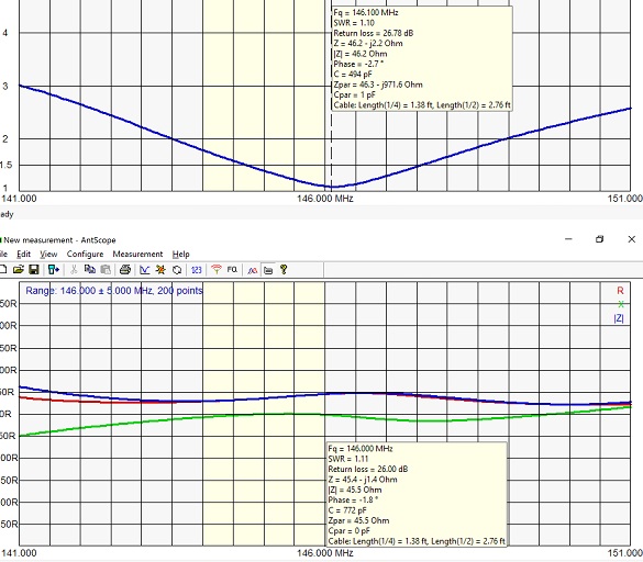
The SWR across all four-Mc of the 2M band is 1.75, which is remarkable for any commercial antenna, let alone home brew.
This antenna is made of 1" EMT tubing, galvanized thin wall steel. Steel is horribly resistive (skin effect) for RF, the zinc coating reduces the skin effect and provides rust-proofing.
The large diameter of the tubing basically zeroes out the skin resistance.
The antenna is soldered at every connection point (except the PL 259 into the socket) so corrosion cannot cause resistive losses and change tuning as the antenna is exposed to the elements.
Thanks to Perry KK4LZF for testing with his antenna analyzer which supplied the graphs below.
Photos:
#1 Antenna analyzer graphs of impedance components and SWR.
#2. Crude work up with lots of poor mechanical joints that made it impossible to tune.The wire loop interacts badly with other metal objects and was only good for a crude estimate of inductance. The final coil was wound excessivly long and tapped to find best tune.
#3 How NOT to insulate the feedpoint. This HDPE food container was quite the capacitor dielectric. PE has a high constant, whereas canned spray foam has a constant almost that of air. Its the same foam used in plugging leaks in houses.
#4 Closer-up of the feedpoint and shunt of the finished antenna. At the top, the 8 inch section of coax braid (gimmick) that caused the system to tune to 50 ohms. It was hopelessly stuck at a 1.5 SWR without it- it absolutely refused to tune any lower.
#5 Overall view
Yes, I can build and ship these if anyone wishes to buy one. Just make sure to have a rotor
.... ..
And now, the HF vertical that is beating the beams and amps. Over the several month period of using it in two States in a bit different forms, this antenna driven by the Yaesu 857 at a max of 100 W, has consistently gotten better signal reports than given against stations with a minimum of 400W amps and large loops up to beam antenna. And that is not just due to propagation which has varied quite a bit, its consistent.
The secret is that there is essentially no better antenna than a vertical, although few Hams may believe that or know anything about them except to string a radial field out in desperation and throw a giant, arcing loading coil across the base.
If properly set up, a vertical can have up to 5.1 dB gain, compared to 2.3 for a half-wave dipole (those are calculated, theoretical figures). It's tempting to believe that impressive looking Yagis on tall towers are the ultimate in gain, but not so, for they suffer from several problems:
1. Feedline loss. Its nearly impossible to put an antenna on a tower without 100-200 feet of coax. Thats a significant loss in power unless rather expensive feedline is used.
2. They are usually mechanically complex with mechanical joints, made of aluminum. The joints corrode both immediately and badly, increasing resistance which causes power loss.
3. A HUGE Yagi is needed at HF frequencies to get much over 7-9 dB gain. Try a Yagi calculator on line and see how much boom length is needed to get 10-12 dB gain.
4. Beam antenna DO NOT RADIATE IN ONE DIRECTION. They are DIPOLES that simple suck up some of the power that would be radiated backwards and send it forward. Don't be deceived by the manufacturers claim of radiation patterns that appear to be that way,
they are showing you the horizontal pattern, look at the THREE DIMENSIONAL RADIATION PATTERNS and notice that like dipoles, beams also waste power up and down.
The vertical, if done properly, does radiate more or less evenly in the horizontal, but not so much up and down. They are often criticized as wasting power sideways, but thats not as bad as wasting it up into space and heating the ground. Dipoles are also more or less omnidirectional. With proper setup, the verticals pattern can be adjusted in elevation also, making them rather directional, just hoping the desired DX station happens to be in that direction.
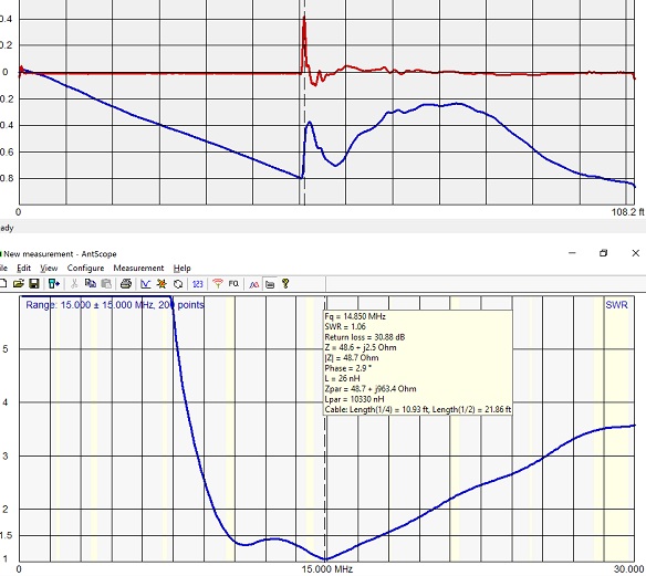
This vertical is 20 feet tall, 'ground mounted', has no radials and only a poor contact with ground through a short, painted metal stake, and seems directional to a lesser extent than the 2M version (the shunt section is very short). What is shocking is that it is self tuning. It has a SWR of less than about 2.5 from 30 to 10M without tuning adjustments such as tapping a coil, it is CONTINUOUS coverage with a 'workable SWR' across about 15 Mc. That is unheard of in the Amateur world for just a vertical pole.
How can it compete or even beat beams and amps? EFFICIENCY. Both of these antennas have zero loss resistance, (well, the HF version has 0.05 ohms calculated...) designed that way by using large diameter tubing with all connections soldered or tightly bonded and since they are not on top of towers, maintaining them is easy. They are also tuned very well, the SWR in the middle of the 2M band and on 20 on the HF version is so close to 1 I can't measure it with 100W forward.
The radiation pattern, at least in theory, I have yet to document the actual patterns on this antenna, especially with the directional gain of the shunt system, should do a much better job of focusing the power in a useful direction that any other antenna except maybe an array.
Verticals are know, falsely, as high noise antennas. This one is extremely quiet, especially as is almost perfectly tuned. It was noticed that when out of tune, the noise was sometimes severe, probably feedline pickup from lying on the ground. As far as power line noise, the vertical is at right angles to the power lines and should couple less noise into the RX than a dipole.
This antenna is much more complex than the 2M version. It is not just a gamma match, there are tuning components/ networks involved. But the traditional loading coil and radials are not present.
This antenna also has the odd feature of being able to be used MOBILE. Ive had it on the Class 3 trailer hitch receiver on the back of the pickup truck on the beach at Ocean Shores WA.


