First, a couple warnings on old radios, and on this one in particular:
1. It is IMPERATIVE that no old radio be operated, even briefly, unless the potentiometers, variable capacitors and switches are disassembled, cleaned/deoxidised and relubricated. All these components will be DESTROYED very quickly without good lubrication AND removing old metal and other debris. The damage is severe, permanent and good luck finding replacements that also must be restored before being used.
From extensive experience working on old radios and TVs, experience shows that 'old' means around 10 YEARS AND OLDER. I've replaced many a tuner and pot in TV's because the grease was gone and they were worn out due to lack of maintenance.
Ten years is not great age on an Amateur radio, but grease is grease, and it doesnt last long.
Grease is two parts, a base or carrier and a lubricating oil. Unless the grease is sealed inside a unit such as abearing, the oil leaves quickly.
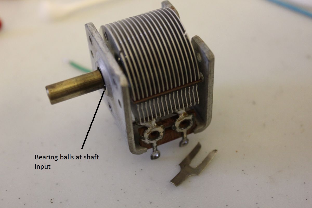
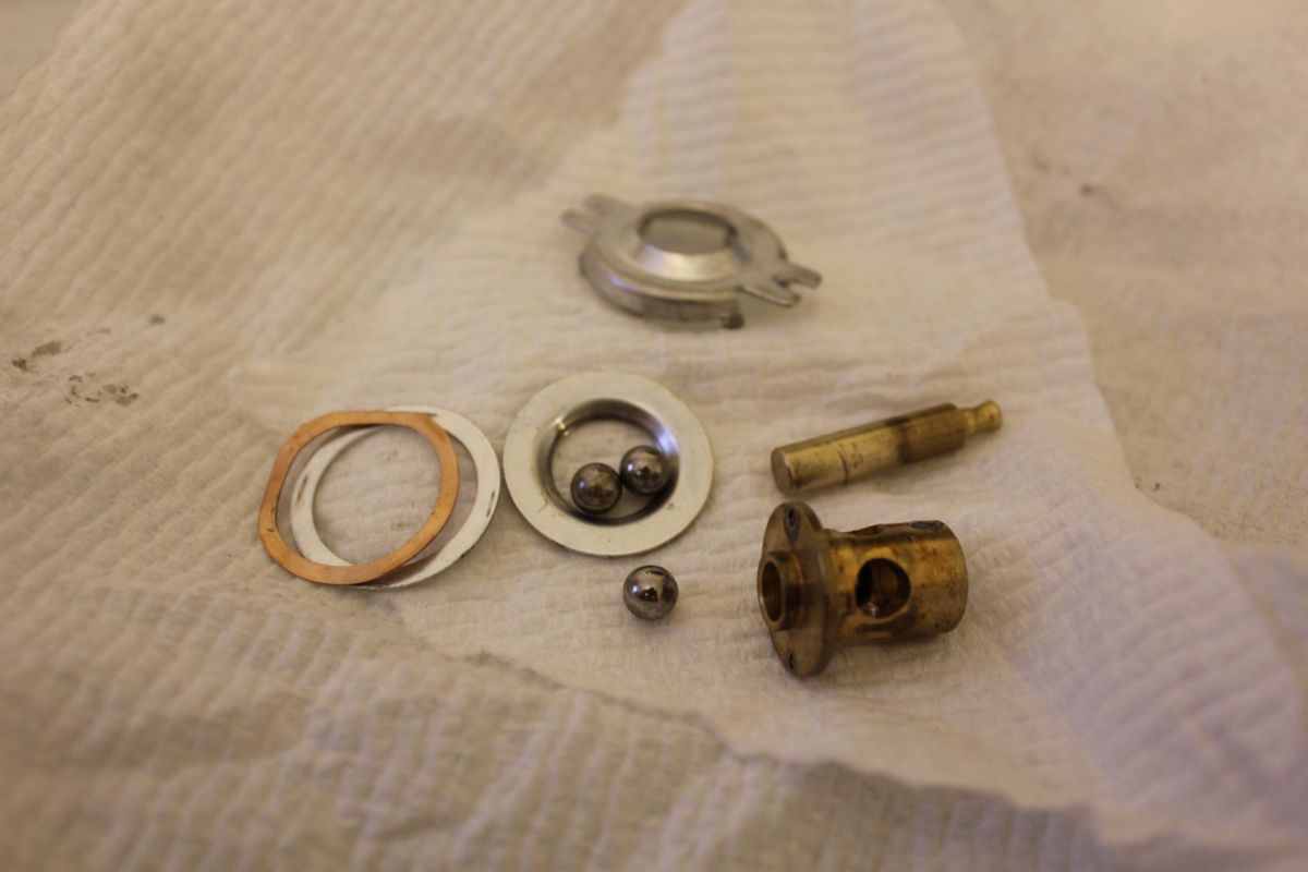
At the front of most air variable capacitors is a ball bearing. The steel balls ride on aluminum or brass races and are much harder than the races, and the mechanical forces the round balls place on them are extreme. Lack of lube will damage the unit severely and very quickly.
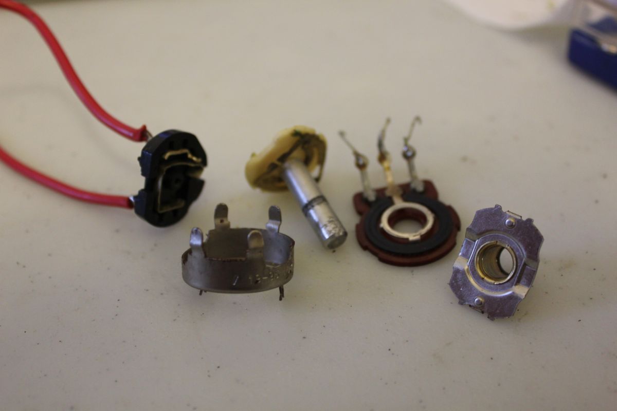
Pots are a particular probelm as the resistive traces are also abrasive, as the material wears off and embeds in whats left of the grease, it forms a grinding compound that must be removed. The result is somewhat like using grease based valve grinding compound on engine valves.
IN NO CASE IS SPRAYING SOME CLEANER AND LUBE ANYWHERE NEAR SUFFICIENT.
NEVER, EVER.
2. Very bad information on the HW-7 from the Internet:
http://www.qsl.net/kk4kf/hw7-mods.html
The HW-7 VFO doesnt need a regulator, that TX did not chirp in the past when the radio was new, try replacing old capacitors and reparing it. Mine does not chirp now because every capacitor in it has been replaced, and engineering knowlege has been applied to that process to make the VFO about as stable as a crystal oscillator-more on that below.
and:
http://k0jqz.blogspot.com/p/blog-page.html
"R 14 in the keying circuit is the wrong value."No it isn't, and it's not a keying circuit, it's 'break- in' and that's a receive function.
Notice the condemnation of Heathkits engineers, stated without proof,
without CIRCUIT ANALYSIS of even a simple DC circuit. The resistor is
NOT the wrong value, it was not in 1976 when I built and used an HW-7,
it's not now, 40 years later after total restoration. These are
uneducated newcomers, well meaning Amateurs, playing a popular Internet
game called Brave New World - they are out to discover what's wrong with
something they know nothing about and to show their genius by correcting others mistakes and by doing so, un edited, without review, on
the instant gratification system called the Internet where the
immediate feedback of seeing this baloney published is an ego booster.
This mod is GUARANTEED to exceed the voltage ratings of that old transistor.
These old transistors had very low voltage ratings. I looked the specs up on this transistor and did the DC circuit analysis on that stage- its Fifth Grade math! The real problem is the
leaky electrolytic cap in the circuit causing excess collector current,
and/or a leaky, or subsequently damaged and leaky transistor. Change the
old failed parts instead of causing another problem and giving false
information to others. Concensus with another Ham who is also grossly
uneducated are two wrongs that do not make right.
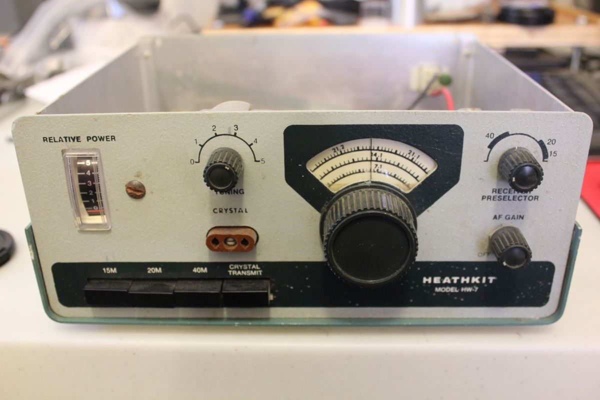
Heathkit HW-7 restoration
The Heathkit HW-7 was a low power, Novice CW rig on 40, 20 and 15M. It was known for good TX signal quality. The front end was rated at 0.5 uV as I recall and had a single dual gate MOSFET for detector, mixer for CW beat and detector. It was a kit. I built this radio around 1976 and due to a mistake in construction, 20 and 15M never worked.
I'd destroyed the front end MOSFET up by taking the shorting spring off before soldering.
NEVER BUY ONE OF THESE OLD MOSFETS WITHOUT THE ORIGINAL SHORTING SPRING IN PLACE TOUCHING ALL FOUR OF THE LEADS.
There are hucksters out there selling them without the shorting spring, pretending that anti static bags are good enough. What they fail to realize is that just the act of removing the spring will destroy that MOSFET and destroy doesnt always mean 'doesnt work at all.' MOSFET gates can suffer punch through. These old MOSFETS had very little or no gate protection and were extremely sensitive to ESD.
Novices back then were required to use crystal control for TX, the rig has a crystal socket on the front panel.
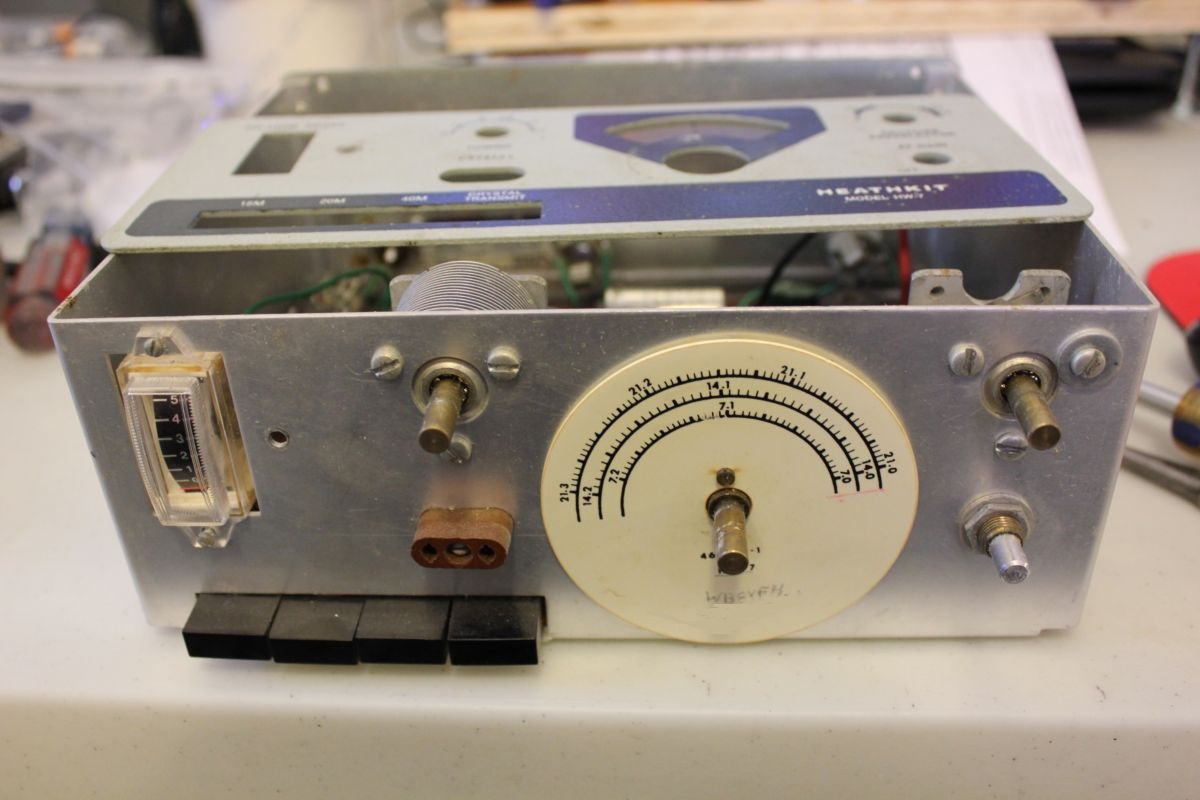
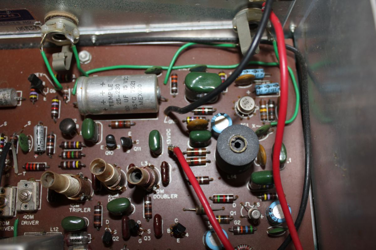
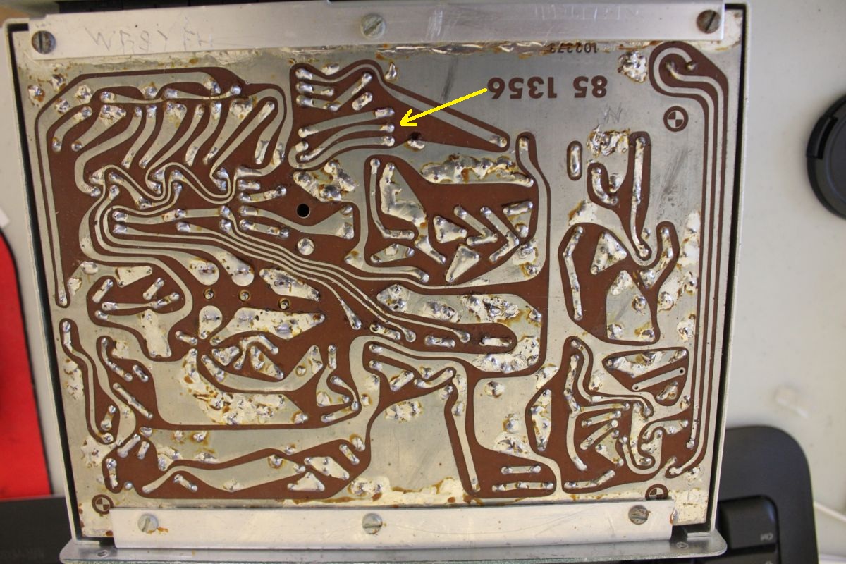
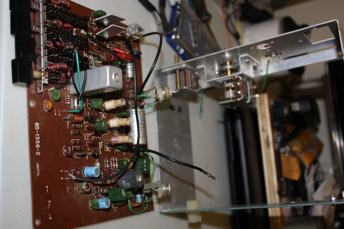
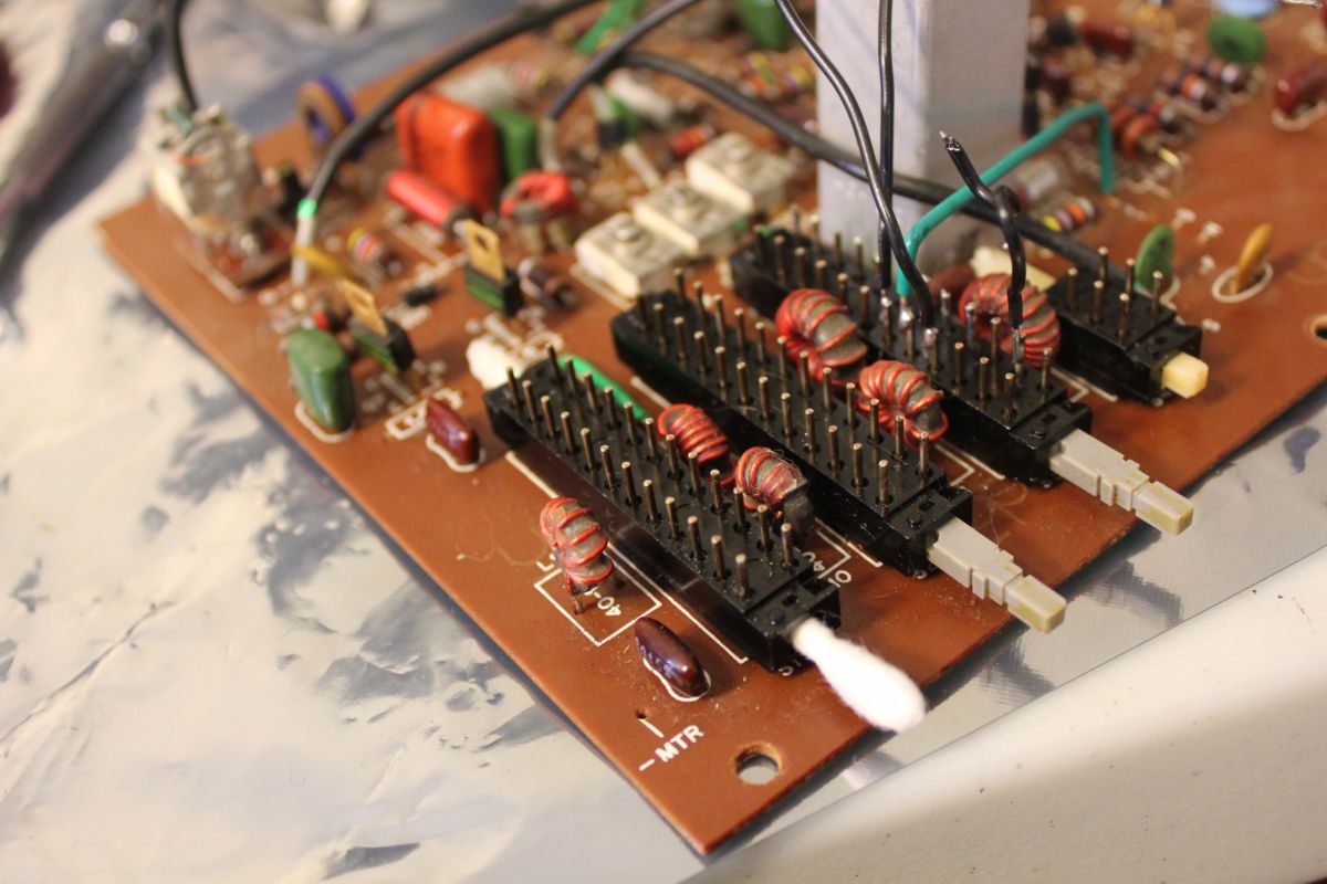
This unit has been totally stripped down, sliding and moving parts cleaned out and re-lubed including the band switch gang, which required partial disassembly of the circuit board, every capacitor except the one in the crystal circuit replaced.
The VFO was reasonably stable for a cheap rig. The manual claims 100Hz in 10 minutes warmup.
The base oscillator is a FET which are not known to be terribly stable, tuned with a two-section air variable across three precision caps, two 1000pF and a 1200.
These caps are the largest values in the circuit. They were replaced with CERAMICS which would have been absolutely un-thinkable in the 1970's as ceramic dielectrics were so poor that they were only good for general purposes. However, modern SMT ceramics in NPO/COG are as close to ideal components as possible (for cheap capacitors, there are better caps) and so were used in the critical places in the rig.
As a result, the VFO is about as stable now as a crystal. The new caps have zero cap change and a tempco of 0.33 ppm, there's almost no way to improve on that. From cold startup, the frequency indicated on the counter is not mearuable, and the LSD of the counter is 10 Hz.
How can it be that a FET oscillator with capacitors is about as stable as a crystal oscillator? The crystal is only as stable as its loading capacitors and the crystal holder capacitance! Crystals are not necessarily used for frequency stability, they are quite temperature and mechanically- sensitive, they are used as they can be ground for precise frequencies.
I'd made one of the biggest bonehead mistakes of my LIFE working on this rig. After reassembled, during tuning and testing, the rig would not work on 15M (it uses a low frequency base oscillator then a doubler/tripler circuit), the highest frequency on the counter across the 15 M tripler circuit was about 14 Mc. After a couple HOURS tracing out every possible cause and finding nothing wrong, it was discovered that the counter was set on LPF.
The seventh picture is the VFO vernier drive which was worn with large brass shavings inside that would have ground away at the parts if the unit had not been totally disassembled, cleaned and lubed.
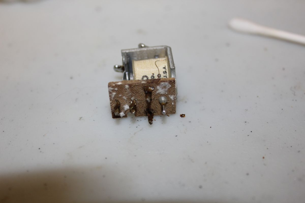
The picture below it is of the TR relay. NEVER put an old rig back on the air that has such a PWB mounted relay, without removing this relay and removing such contamination from under-neath usually left behind as a result of WATER condensing under the warm relay coil- it can lead to RF leakage or arcing. Coaxial cable can conduct water down between the conductors and insulators (any insulated wire can, but coax usually has a far end exposed to rain) and if the coaxial socket is not sealed, water can travel down the inside of the cable and into the radio and may end up under the relay.
In the third picture from the bottom, the RG174 cable from the TR relay to the preselector goes across the circuit board, I shortened it so it didn't run along the back of the chassis as in the assembly manual. MISTAKE. It interacts with the VFO can and its position near the can changes the VFO frequency. It'll work Ok as long as the cable does not move.
Pix # 11 the surface mount NPO capacitors on little snippets of printed wiring board. The board segments are attached to the main PWB with soldered leads, then the SMT caps soldered to the segments.
