
UHF DUMMY LOAD
Yes, MFJ sells something that look s like this, but it may not work like this!
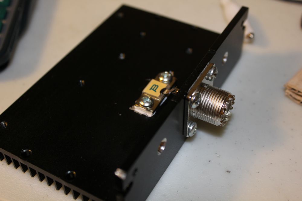
The 250W microwave terminator is not a resistor. Using it for that for low frequency work brings the surprise that its not 50 ohms as the Digi Key ad claims, but 48.9 ohms. Its a resistor and a few pF capacitance.
This microwave terminator is an ideal dummy load element as it has very small parasitic values, about 4 pF as measured on my cheap LCR meter, and some extremely small inductance.
The terminator may be 50 ohms at 2 GHz, but Im using it at HF/VHF, and it's not 50 ohms there. So, precision low inductance SMT resistors have been added (not in the photos) to correct the impedance to 51 and change. The error is so small it cant be measured at 100W. Running the Jug, yes, but this wont handle 1500 watts so that's irrelevant. At 1500W, a 1.1 SWR becomes noticeable.
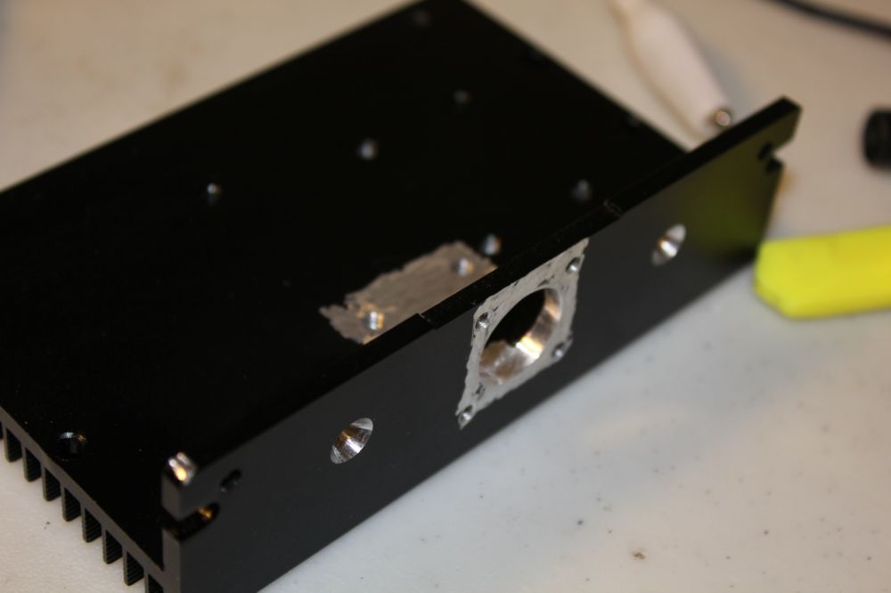
The SO connector is why its not a microwave load. They are barely good enough for VHF work.
The housing formerly held a stepper motor board which I fried. The heat sink may not be good ehough for 250W continuous, but that could be improved by setting the heat sink fins in a pan of water. We Amateurs sometimes must find creative ways to deal with problems, especially on Field Day...
Total cost, about $30.
BETTER CONNECTOR, BETTER CONNECTION- EZ 400 COAX PLUG
The PL 259 connector has been the standard coax connector for decades but they are next to impossible to solder on the feedline, as the shell is massive and requires a lot of heat to raise to soldering temperature (if the shield is to be soldered). That heat usually damages the dielectric in the cable.
The Times Microwave EZ 400 connector is far superior, with a removable center pin for soldering and Ive found a unique way to connect the shield, on the OUTSIDE of the connector shell, so that wire fragments that break from the shield cannot find their way into the connector and short across the center pin.
A special industrial clamp is used to clamp the shield to the outside of the connector shell. The clamp and shell are removable and replaceable in the event the cable is to be passed through, for example, a small hole in a window.
The connector is intended to be assembled with an included plain steel sleeve that is swaged onto the shell with a hex crimp tool. They are impossible to remove without destroying the sleeve and do not have as much contact area as this round clamp, so the clamp should have lower resistance.
The trick to preparing the feedline is to use a plumbing tubing cutter (as used to cut copper plumbing tubing) to score the coax jacket without the risk of a knife cutting through and damaging the shield- that is where little braid wire fragments come from that can eventually cause a short inside the connector.
The center pin was removed using a drill press as a press. The pin was soldered onto the center wire which was tinned. The center pin must be soldered as there is no other way to prevent oxidation of that press in connection long term.
This connection with the EZ connector results in an almost perfect electrical termination, see the antenna analyzer graph for the HF vertical- its feedline has a connector put on by this method. There is barely any reflection at the connector.
Beware of using cheap versions of this LMR 400 cable, they have an aluminum center wire that has a copper flashing- once the copper is gone, its impossible to solder to the wire. The cheap stuff is 90 cents, the real LMR is 1.20.
